Fire Detection and Alarm System (FDAS): Bosch AVENAR panel 2000
Life-safety installation — kindergarten & school, Slovakia
01 / Overview & Standards
Installation, LSN loop programming and building integration of the fire detection and alarm system (FDAS; Slovak: elektronická požiarna signalizácia, EPS) for a kindergarten and school in Slovakia. The FDAS controller is a Bosch AVENAR panel 2000; door holders, the main power distribution and a GSM dialer are controlled by an RML 0008 A relay module on the panel's internal rail.
The project design (device layout, rooms and the cause-and-effect logic) was prepared by the team and the authorized supervisor, who holds the required authorization and is responsible for it. I installed, addressed, programmed and troubleshot the system on site.
- Readable alarms: the panel shows functional zones and room names, not raw LSN bus addresses.
- Fail-safe controls: escape doors release on alarm and on loss of power.
- Battery autonomy to EN 54-4: 24 h standby plus 30 min alarm.
| Reference standard | Scope |
|---|---|
| STN EN 54-2 | Control and indicating equipment |
| STN EN 54-3 | Fire alarm sounders, acoustic parameters |
| STN EN 54-4 | Power supply equipment and battery sizing |
| DIN 33404-3 | Evacuation tone: falling sweep 1200 → 500 Hz in 1 s |
Qualifications
Certified Designer & Engineer – Fire Alarm Systems / EPS (Bosch FPA 5000/1200, AVENAR)
ManufacturerManufacturer (Bosch) certification, issued by Bosch Building Technologies Europe, Mar 2026.
§21 (Vyhláška 508/2009 Z. z.)
RegulatorySlovak Decree No. 508/2009 Z. z.
02 / Hardware & Topology
| Role | Device | Notes |
|---|---|---|
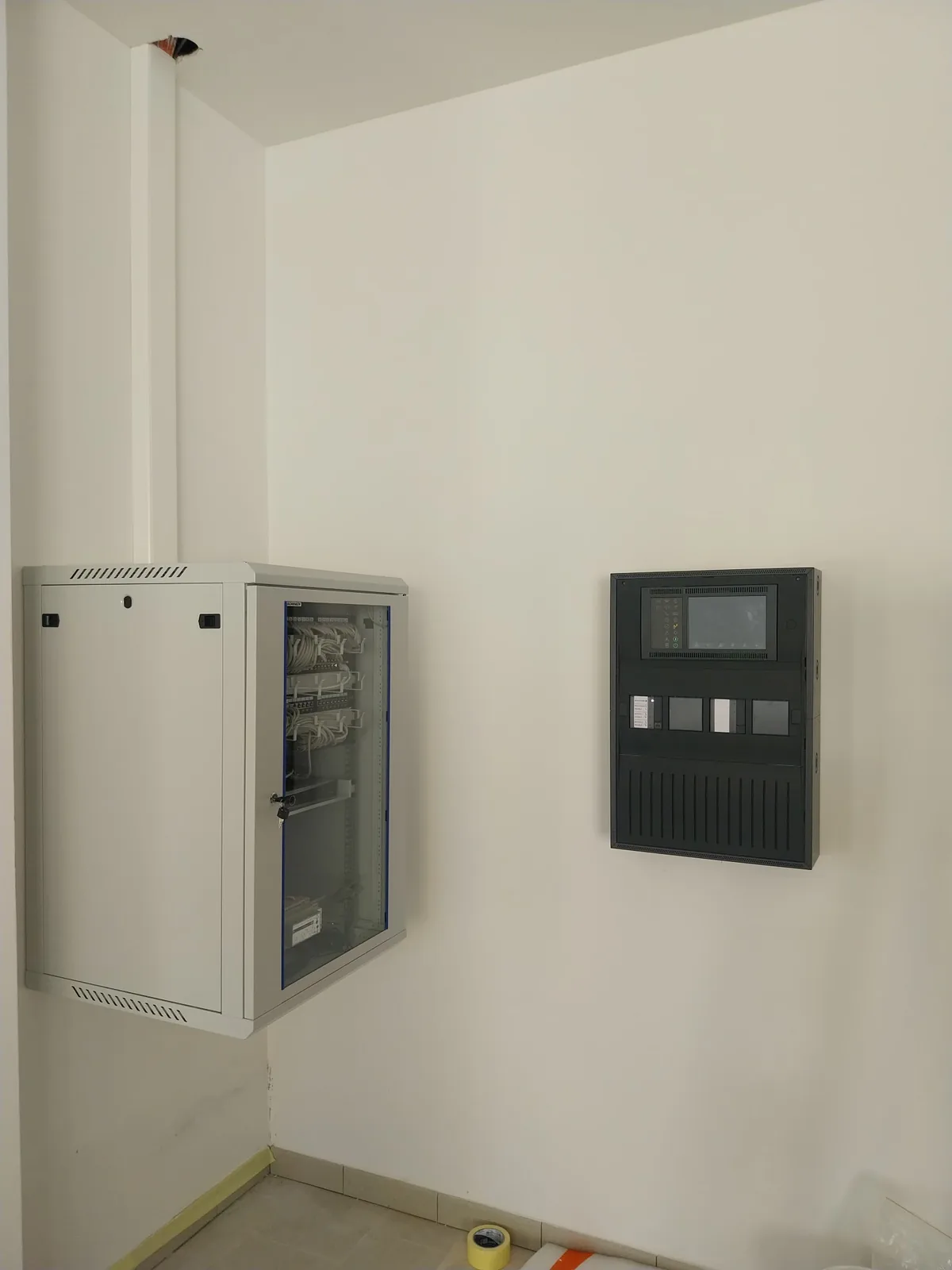
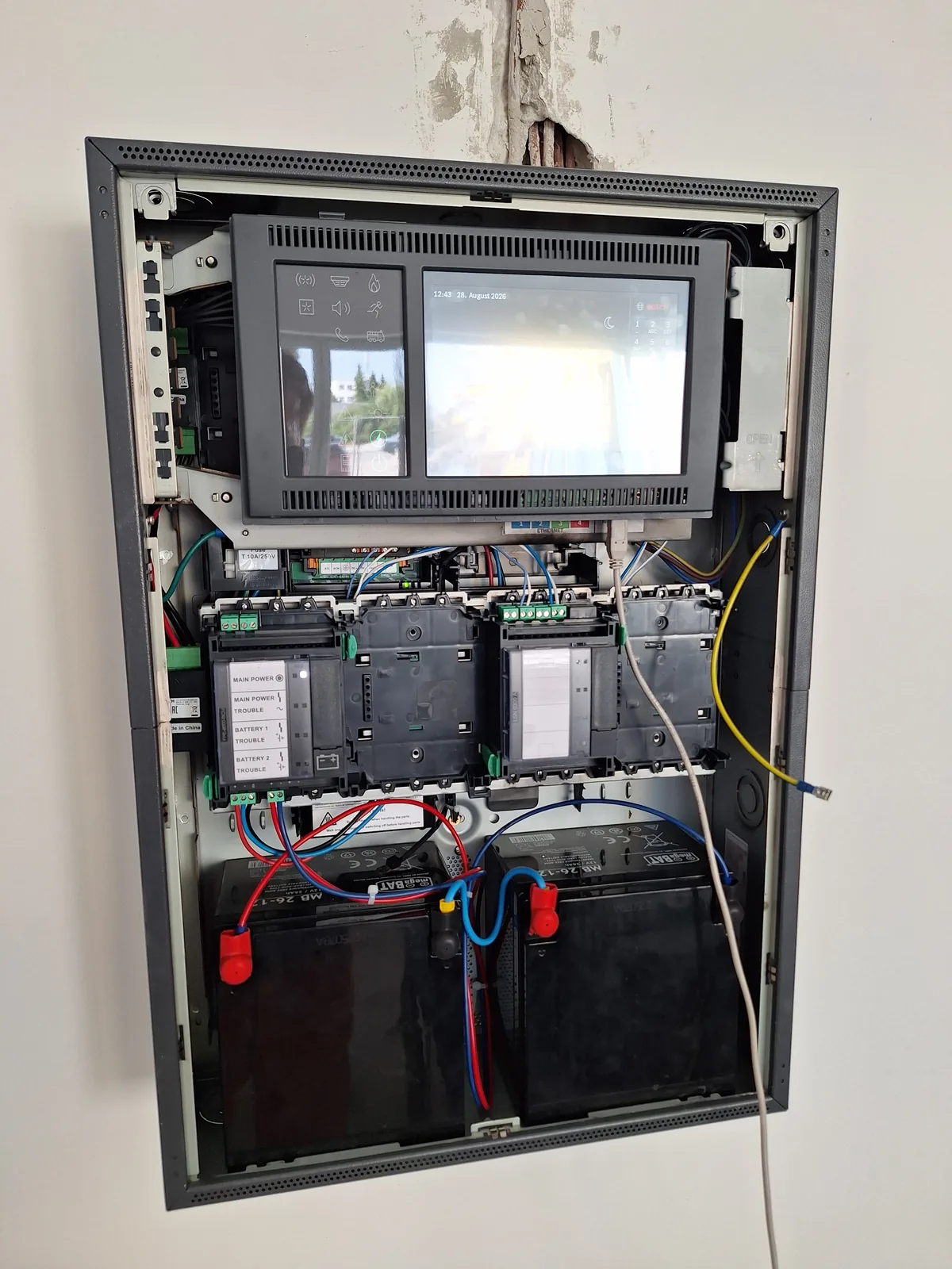
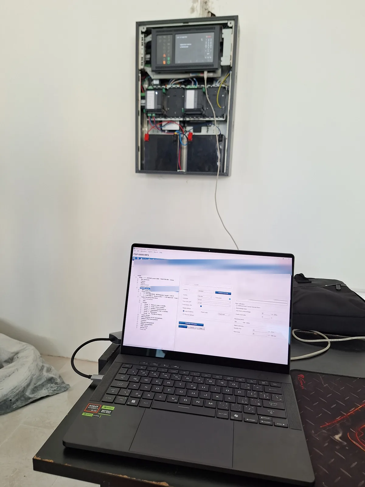
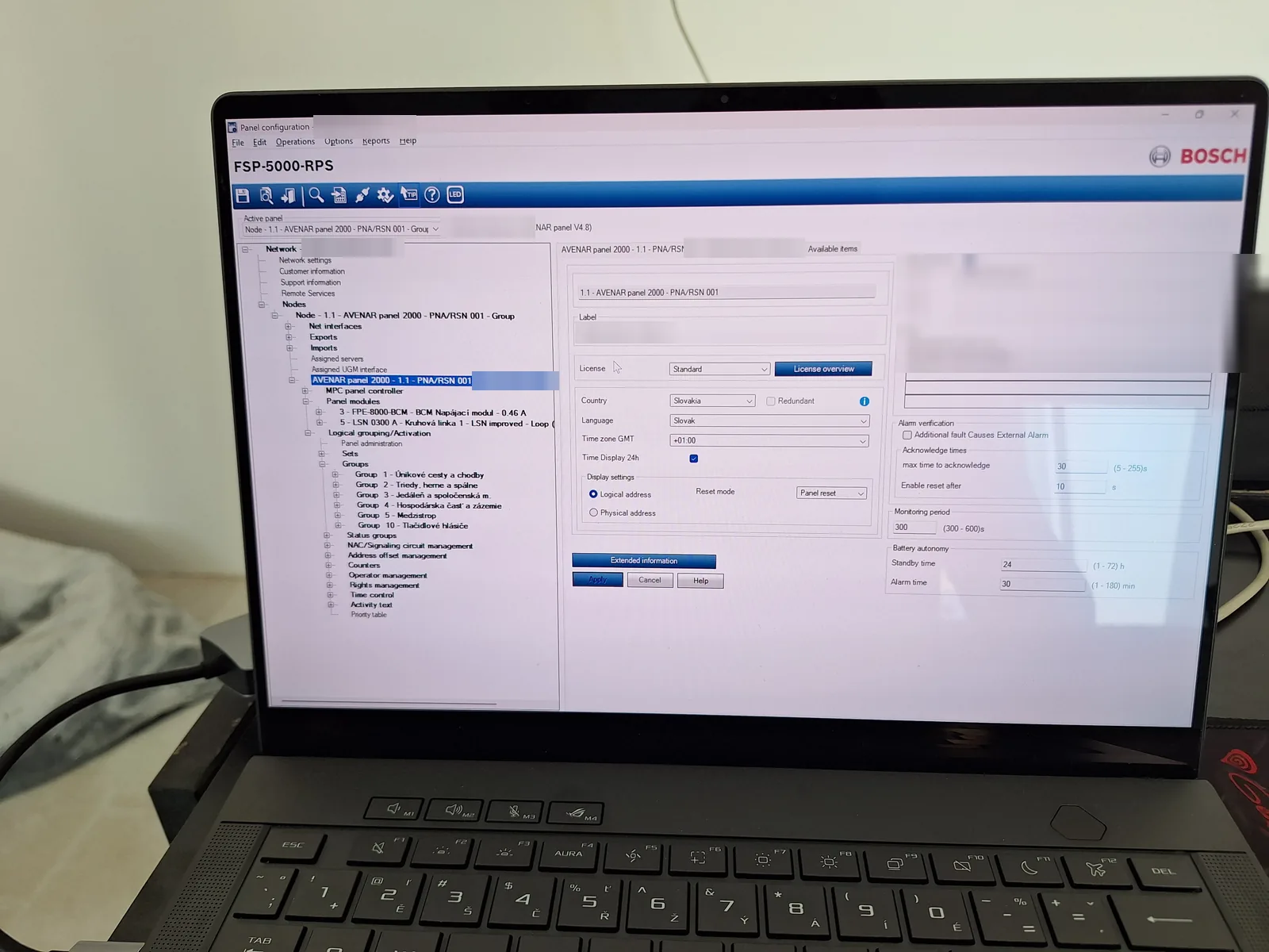
| FDAS controller | Bosch AVENAR panel 2000 | Node 1.1, programmed in RPS. Touchscreen with zone map and contact details. |
| Power | FPE-8000-BCM | Battery controller on rail position 1. 24 V DC, 2× 12 V 26 Ah SLA in series. |
| Loop controller | LSN 0300 A | Rail module. Closed LSN ring. |
| Relay outputs | Bosch RML 0008 A | 8-relay rail module on the panel's internal rail (not an LSN field device). |
| Detectors | FAP-O420, FAP-425 | Optical smoke detectors. |
| Strobes | FNS-420-R | LSN visual alarm devices. |
| Sounders | FNM-420U-A-BS | LSN base sounders. |
| Addressable MCPs | Bosch FMC-420RW series | Addressable manual call points (MCP), surface-mounted. Reset mechanism, status LED, top-hinged cover opened with a service key. |
| DC-DC converter | Mean Well DDR-15G-12 | 24 V → 12 V, isolated, DIN rail. Feeds the GSM dialer. |
| Dialer | GSM / SMS module | Installed inside the metal panel cabinet. |
Photos
03 / Zoning
Alarms are displayed by functional zone and room name instead of LSN addresses such as Node 1.1, Dev 38. The zone names below are exactly what the panel display shows, so staff or the fire brigade can read the location of the fire in seconds.
| Zone | Display name (SK) | Area | Devices |
|---|---|---|---|
| Zone 1 | Únikové cesty a chodby | Escape routes and corridors | Smoke detectors, sounders, strobes |
| Zone 2 | Triedy, herne a spálne | Classrooms, playrooms, dormitory | Optical smoke detectors (FAP-O420), base sounders |
| Zone 3 | Jedáleň a spoločenská m. | Dining hall, common areas | Optical detectors for large rooms, wall sounders |
| Zone 4 | Hospodárska časť a zázemie | Service area, utility rooms | Heat and smoke detectors |
| Zone 5 | Medzistrop | Ceiling void above suspended ceilings | Concealed optical detectors with remote indicators |
| Zone 10 | Tlačidlové hlásiče | Manual call points (MCP) | Bosch FMC-420RW addressable MCPs |
04 / Cause & Effect
The cause-and-effect logic is part of the project design by my colleagues; my part was implementing the relay outputs (RML 0008 A).
Building functions are driven by the RML 0008 A relay module on the panel rail.
| Output | Normal state | On fire alarm | On power loss |
|---|---|---|---|
| Door holder magnets | Energised, escape doors held | Relay cuts the supply, doors release mechanically | Released (fail-safe) |
| Main distribution | Shunt trip idle | Shunt trip (vyrážacia spúšť) fires, non-essential 230/400 V circuits are switched off | Not applicable |
| GSM dialer | Dry NC loop closed | Loop opens, the dialer sends the alarm | Stays powered from the battery-backed AUX rail |
The dialer sits inside the metal panel cabinet, so the dry NC loop never leaves the enclosure and a cable break is practically excluded; any opening of the loop triggers it immediately. It is powered from the 24 V AUX rail through an isolated Mean Well DDR-15G-12 (24 V → 12 V), not from a single battery, which would unbalance the series battery set.
05 / Technical Challenges & Troubleshooting
Working in a closed industrial system
Bosch AVENAR, RPS and LSN are closed life-safety products. Unlike open-source web technology there is minimal public documentation, no Stack Overflow coverage and no useful AI training data on their internal logic or error codes.
The work relied on reading the engineering schematics and manufacturer documentation, multimeter measurements on the loop, and hands-on fault isolation.
Rail module order and bus power
The panel failed its initial internal hardware validation. The modules were seated in the wrong order on the internal rail (PRS-0002A).
The panel backplane enforces a fixed physical order: the battery controller feeds power into the rail, and the other modules are arranged by current draw to avoid voltage drops on the internal DC bus and logic arbitration faults.
Modules re-seated in the required order: FPE-8000-BCM in slot 1 next to the power feed, then the LSN 0300 A loop controller, then the RML 0008 A relay module. Hardware validation passed.
rail position   module          role
1               FPE-8000-BCM    battery controller · power feed
2               LSN 0300 A      LSN loop controller
3               RML 0008 A      8 relay outputs
Base sounder wiring: schematic vs. hardware
The FNM-420U sounder bases stayed silent and caused a continuous loop fault.
The schematic required a manual jumper between two base terminals. The current hardware revision bridges these internally, so the obsolete jumper interfered with LSN line monitoring.
Removed the jumper and returned to a clean LSN line. The sounders became addressable immediately and the line fault cleared.
Locating a loop fault with T-tap mode
The closed LSN ring would not come up; devices reported short circuits and lost communication.
In a ring the panel communicates from both ends, which hides where the fault actually is.
- Panel temporarily switched to open (T-tap / stub) polling.
- Devices were addressed one after another along the cable; the scan stopped at the faulty point.
- At that detector the terminal screw had pinched the insulation instead of the bare conductor. Re-stripped 8–10 mm, rescanned to the last device and closed the ring again in RPS.
BCM energy limit exceeded (72 h vs. 24 h)
RPS reported:
Fatal: Energy Zone 1 power consumption
exceeds the maximum limit (FPE-8000-BCM)
Standby time had been set to 72 h. The standby current is 0.46 A and the battery set is 2× 12 V 26 Ah in series, which gives 24 V 26 Ah — capacity does not add up in series.
Standby time set back to 24 h + 30 min alarm, the autonomy specified for this building. The RPS consistency check passed.
usable capacity   26 Ah × 0.8          = 20.8 Ah
72 h standby      0.46 A × 72 h        = 33.1 Ah   > 20.8 Ah   ✗
max. at 72 h      20.8 Ah ÷ 72 h       ≈ 0.29 A    < 0.46 A    ✗
24 h standby      0.46 A × 24 h        = 11.0 Ah   + 30 min alarm  ✓
06 / FDAS Commissioning Checklist (technical self-check)
FDAS COMMISSIONING CHECKLIST (TECHNICAL SELF-CHECK)
Status: INSTALLED, PROGRAMMED & TECHNICALLY VERIFIED
Reference standards: STN EN 54-2, 54-4 | DIN 33404-3
SYSTEM CHECKS:
24 V 26 Ah SLA bank checked for 24 h standby + 30 min evacuation.
Obsolete sounder jumper removed; terminal fault located via T-tap.
FMC-420RW manual call points and optical strobes functional in testing.
shunt trip (230/400 V mains cut) and isolated NC GSM telemetry.